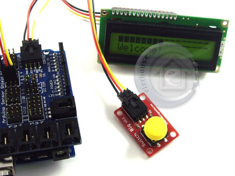
Flamingo Eda Serial Lcd

SENSOR SHIELD: An easy way to connect many INPUT DEVICES and OUTPUT DEVICES to Arduino. Not just sensors! SENSOR SHIELD VERSION 4: See See The Sensor Shield's purpose is make it easy to connect cables and devices to the correct Arduino pins. It is not an active device. It simply connects the Arduino pins to many connectors that are ready to use to connect to various devices like Servos and Sensors with simple cables. YourDuinoRoboRED: 'Built-In Sensor Shield Connectors': On the right is the Arduino-compatible board.
It has the 3-pin connectors similar to a Sensor Shield built-in. YourDuinoRobo1: 'Built-In Sensor Shield Connectors': On the right is the Arduino-compatible board.
It has the 3-pin connectors similar to a Sensor Shield built-in. The top connector has 3 colors: Black=Gnd, Red=+5V, White=Signal. You will see that this matches the colors on the 3-pin cables. The bottom connector is for the Analog Inputs, and has Gnd - +5V - Signal in the other direction.
NOTE: Shown above is which is commonly used. Lionel Richie Tuskegee Album Mp3 Download. SENSOR SHIELD VERSION 5: Below is, which is the same except 2 communications ports are provided to use Serial and I2C communications simultaneously.
NOTE: There is also a Sensor Shield for the Arduino MEGA and at the bottom of this page. Each Port has 3 pins which are connected to (Ground), (Vcc + 5 V) and (Signal). See the GVS labels above. Cables normally are color coded so you know the right way to plug them in: Ground Black Voltage Red Signal White or Yellow DIGITAL I/O PINS 0 to 13: These are available in the rows outlined in red above. They connect with cables to Electronic Bricks and other INPUT DEVICES and OUTPUT DEVICES. ANALOG INPUT PINS A0 to A5:a These are available in the row outlined in white above, AND on the black 'Latched' connectors labeled 'Analog 0' to 'Analog 5'.
They also connect with cables to Electronic Bricks and other INPUT DEVICES. COMMUNICATIONS PORT: This connector can go to external Bricks or other devices that have more complex Communications Protocols to work with Arduino. Examples are GPS receivers, Ethernet interfaces, and other complex devices. These are 4-pin connectors. Either SERIAL COMMUNICATIONS (COM) or 'I squared C' (often written as I2C or IIC) are supported on V4.
The two selectjumper blocks shown above are moved to select one or the other. On V5 there are separate connectors for SERIAL and I2C Communications. Other cables can connect, like these examples: The Arduino MEGA has many more I/O pins (54 Digital pins and 16 Analog pins)than a standard Arduino. This shield also has connectors specifically for some external devices like an SD Card, Radio communications (Bluetooth and others). It also has an option to power the 'V' pins on all the Digital I/O 3-pin groups from an external power supply instead of the Arduino +5V. This is good for large numbers of servos etc.
DISPLAYS: LCD + (10) SERVOS+MOTORS (18) IC's, OptoElectronics, LEDs, Regulators (57) ELECTRONICS PARTS Assortment Kits (29) RESISTORS-CAPACITORS (28) COMMUNICATIONS: Wireless, Bluetooth, Internet, GPS, Serial, RS485, IR (26) ELECTRONIC BRICKS (61) SENSORS + SWITCHES.
The 'Analog' 3-pin groups still use the Arduino +5V which is better from an electrical noise perspective. This version has two options of +5V supply to all the 'V' pins: • Jumper on: +5 comes from the Arduino.
Should be limited to about 300 ma • Jumper off: +5 (or other appropriate voltage) comes from an external supply connected to the blue terminal strip. External power Ground must also be connected to the blue terminal strip. Using an external supply allows more current than the Arduino or Mega can supply, such as current for control of many servos or relays, and other attached devices.
Usually this is +5V because most external devices require it. It is possible to use +6 volts if ALL the attached devices are the same such as Servos with that rating. Dedicated Connectors (pins left to right, top to bottom, per above picture) • ICSP: RST, D52/SCK, D50/MISO, GND, D51/MOSI, 5V • Bluetooth: 3V3, GND, D0/RX0, D1/TX0, GND, 5V • SD Card: D50/MISO, D52/SCK, D53/SS, D51/MOSI, 5V, GND • APC220 (Wireless): --, D19/RX1, D18/TX1, --, 5V, GND • URF01 (ultrasonic): 5V, D48, D49, GND.
Hi folks, Just received my Yourduino order and a little confused. This is the Yourduino Serial LCD but does not match the info and photos on the Yourduino site. I need help in getting this to work. I have tried googling the flamingoEDA name and havn't found any matches in English sites.
It looks awfully like I2C to me whereas I want to use this as +5V, 0V and signal only. After checking with a magnifying glass the socket to the right of the photo is labelled (top down) -, +, R, T so I am assuming that I only need to wire the top three contacts?
Would love to know the required setting of the DIP switches (baud rate?) and use of the left hand connectors. Any enlightenment woul be much appreciated.